Last summer, a food processing plant in Ohio lost an entire production shift. The culprit? Not a transformer failure, not a protection relay misoperation — but a discolored, overheated connection finger inside a 480V withdrawable breaker compartment. It had been gradually loosening for months, generating enough heat to warp the insulating support, until one night the contact resistance tripped the thermal limit. The part itself was small; the cost of stopping three packaging lines was not.
Maintenance logs across industries paint a similar picture. From data centers to water treatment plants, withdrawable switchgear assemblies are praised for flexibility — you roll out a functional unit, perform a quick swap, and restore backup power with minimal handling of busbar compartments. But that same convenience hides a chronic weakness: the mechanical interface where the removable drawer meets the fixed busbars. If that interface degrades, you are looking at a string of nuisance trips, forced cooldown periods, or panel fires that a simple thermographic survey might miss.
This article walks through why those connections loosen, how to spot early warning signs before the next shutdown, and what engineering decisions actually prevent the problem — without resorting to “just tighten it again” rituals that seldom last.
When a switchgear cubicle shows elevated joint temperatures, the default first move is to re-torque the contact assembly. It makes sense: vibration, load cycling, and thermal expansion work screw connections loose over time. Yet in a sizable number of cases, the screws are still at factory spec — the loss of clamping force originates somewhere else.
Three mechanisms tend to work together:
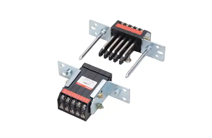
Fretting corrosion at the interface. Drawer contacts rely on multiple spring-loaded fingers pressing against a stationary busbar stub. Under microscopic movement (induced by mechanical shocks from breaker operation or floor-borne vibration), the protective plating wears through. Bare copper or silver-plated surfaces oxidize, and the contact resistance climbs before any visible damage appears. This is a well-documented degradation pattern in IEC 62271-1 temperature-rise tests, where contact resistance drift often precedes thermal runaway.
Spring relaxation in contact elements. Stainless steel contact springs are not immune to stress relaxation, especially inside compartments that run near the 105°C limit for hours every day. After a few thousand thermal cycles, the contact force can drop enough that the finger loses its wiping action during insertion. The drawer feels normal when racked in, but the electrical connection is already borderline.
Misalignment from worn guide rails. Withdrawable units ride on telescopic rails that accumulate wear over decades. When the drawer sags by even 1–2 mm, the cluster of contact fingers no longer mates symmetrically with the fixed stub. The outer fingers carry disproportionately high current, accelerating localized heating and insulation embrittlement.
None of these issues disappear with a torque wrench alone. Recognizing the specific failure mode determines whether the next corrective action is a simple cleaning, a rail adjustment, or a full replacement of the contact set.
Waiting for a breaker trip or a melted arc chute is the most expensive detection method. The following checks, integrated into scheduled outage windows, catch most incipient failures:
Visual under magnification. At the next rack-out, use a borescope or a high-res camera instead of relying on the naked eye. Look for loss of silver plating, lateral score marks that indicate misaligned insertion, and greyish powdery oxide deposits around the contact zone. If more than 15% of the contact area has lost its plating, the set has moved into accelerated degradation.
DC resistance baseline. A micro-ohmmeter reading taken across the drawer-to-busbar joint (not just the breaker poles) can reveal contact degradation before thermography. Record the value on commissioning, then trend it at each major shutdown. A 20% rise from baseline — without corresponding changes in ambient temperature — justifies deeper inspection.
Insertion force measurement. A few utilities now use portable force gauges to measure the effort needed to rack a drawer into the service position. A sudden drop in insertion force, compared with the unit’s own historical readings, points to compromised contact spring pressure.
When one of these indicators moves in the wrong direction, schedule a more detailed examination. Acting on early electrical signatures typically turns a 12-hour emergency repair into a two-hour planned replacement.
Maintenance teams can buy time with careful servicing, but the overall reliability ceiling is set by the contact system’s material and design. Two parameters matter more than most field technicians realize:
Plating type and thickness. Silver plating remains the standard for drawout connectors carrying above 630A, thanks to its conductivity and oxide-free surface. But silver’s hardness also makes it susceptible to fretting wear under micromovement. High-cycle applications benefit from contacts with a silver-graphite or silver-alloy top layer, which sacrifices a few points of conductivity for lower friction and longer wear life. When evaluating replacement parts, ask for the minimum plating thickness under ASTM B700 or an equivalent norm — thin flash coatings disappear quickly in switchgear that undergoes monthly rack-out cycles.
Spring material and geometry. Constant-force springs maintain contact pressure over a wider tolerance band than conventional helical springs. They compensate for wear-induced dimensional changes without the drastic force drop seen in simple compression designs. This design nuance frequently separates components rated for 1,000 mechanical operations from those barely surviving 200 before overheating appears.
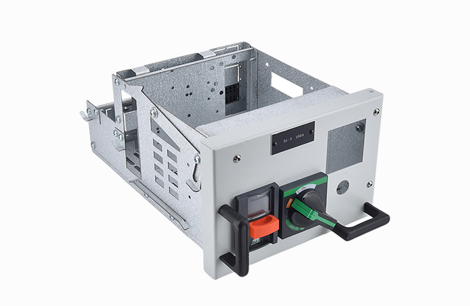
The catch: evaluating these material choices requires cutting through catalog claims. Specifying a reliable component for a drawer unit or similar assembly often comes down to supplier data transparency — documented temperature-rise tests, plating thickness certification, and mechanical endurance reports under cyclic loading. This is precisely where the choice of component partner shifts from a purchasing decision to an engineering one. Viewing a line-up of durable drawer contact solutions tested under cyclic thermal loads can clarify what performance documentation you should expect from any supplier, whether or not you adopt that specific product.
Assume a withdrawable cubicle has been flagged — rising DC resistance, visual plating wear, but no structural damage yet. A methodical intervention, performed during a planned shutdown, follows this sequence. It avoids the common trap of cleaning contacts and ignoring the mechanical system around them.
Rack-out and isolate. Follow full LOTO; verify zero voltage on both the drawer side and the fixed busbar side. Record the ambient temperature for later resistance comparison.
Document the as-found condition. Photograph all contact surfaces, measure insertion depth and any lateral play in the guide rails, and note whether the shutter mechanism opens evenly.
Clean with appropriate agents. Use a dedicated silver contact cleaner, not generic degreaser. Abrasive cleaning should be limited to products recommended by the contact manufacturer — aggressive emery cloth leaves deep scratches that become future oxidation sites. After cleaning, check the plating thickness if a gauge is available.
Address the rails before reinstalling the contact set. Worn guide rails create the misalignment that kills new contacts prematurely. Adjust or replace rails to restore alignment within the switchgear OEM’s tolerance (often ≤ 1.5 mm vertical sag at full extension). Lubricate with an insulating, oxidation-resistant grease compatible with the operating temperature range.
Install the replacement contact set and verify alignment. A correctly seated set shows even compression across all fingers when viewed from the busbar side. Use a feeler gauge to confirm symmetrical engagement.
Rack in slowly, feeling for abnormalities. Resistance that increases abruptly midway through racking usually signals a shutter interference or a misrouted secondary disconnect cable binding the drawer.
Perform a final resistance check and document. Compare to the original baseline. If the value is still elevated, recheck rail alignment and busbar stub condition — the root cause may sit deeper.
This sequence treats the connection as a system, not a consumable part. It’s the difference between a fix that lasts six years and one that returns as a work order next season.
A segment of the market relies on commodity contact parts — generic fingers, springs, and cluster assemblies that promise compatibility but deliver short service intervals. Where the environment is benign and cycle counts are low, such parts may work adequately. The calculation changes when the application involves:
More than 24 mechanical rack-out operations per year,
Sustained ambient temperatures above 40°C,
Harmonic-rich loads that increase heating in the neutral and phase connectors,
Or arc-flash boundary constraints that penalize any unexpected rework.
In these scenarios, the cost structure inverts. Spending an extra few hundred dollars on a rigorously tested set of connection components — complete with certified temperature-rise data and documented spring-force retention curves — becomes a bargain compared with a single unplanned outage event. The reliability margin moves from hope to documented engineering.
This is the philosophy that MOLDVOLT has baked into its power distribution components. The company’s range of cabinet accessories for withdrawable switchgear is built with a focus on transparent material specifications and published endurance data — so facility engineers can compare what they are buying against the duty profile they actually have, rather than a generic catalog rating. If your maintenance records show more than a few unscheduled drawer inspections this year, it may be time to review the configuration options available and match a contact set to your real operating conditions.
Preventing loose drawer connections is less about heroic maintenance and more about institutional memory. Three habits have proven most valuable in facilities that run switchgear for decades without major connection failures:
Trend, don’t just inspect. Move thermographic and micro-ohmmeter readings from clipboard checkmarks to trended databases. A slowly rising joint resistance that is still within absolute limits is the strongest predictor of future failure. Set alarms on the rate of change, not just fixed thresholds.
Write a connection-specific maintenance SOP. Generic switchgear procedures often gloss over contact evaluation. Create a one-page standard that details visual criteria, plating condition pass/fail rules, rail wear tolerances, and the precise cleaning agents approved for your equipment.
Manage the parts room like a reliability program. Know the manufacturer’s batch traceability for installed contact sets, record installation dates, and stock the exact replacement sets identified during the last engineering review. Mixing and matching parts from different generations of the same switchboard has caused more outages than most electrical engineers care to admit.
None of this requires exotic technology. It’s discipline, supported by components that don’t add their own performance mysteries to the equation. If you are looking to anchor that discipline with components that come with clear performance documentation, explore MOLDVOLT’s switchgear cabinet accessory lineup and see whether the specifications match your electrical and mechanical demands.
IEC 62271-1:2017 – High-voltage switchgear and controlgear – Part 1: Common specifications for alternating current switchgear and controlgear
ASTM B700 – Standard Specification for Electrodeposited Coatings of Silver for Engineering Use
EPRI Report 3002015813 – Condition Assessment of Medium-Voltage Switchgear: Strategies for Electrical Contact Monitoring
Disclaimer: This article provides general guidance based on industry practice and does not replace manufacturer-specific service instructions. Always follow your equipment OEM’s procedures and applicable safety regulations during maintenance activities.
pubdate: 2025/10/09 2026/06/30
Solve Loose Plug‑in Contact Connectionpubdate: 2025/10/09 2026/06/23
4 Common Insertion Mistakes That Void Warrantypubdate: 2025/10/09 2026/06/15
5 Factors for Choosing a Drawer Cabinet