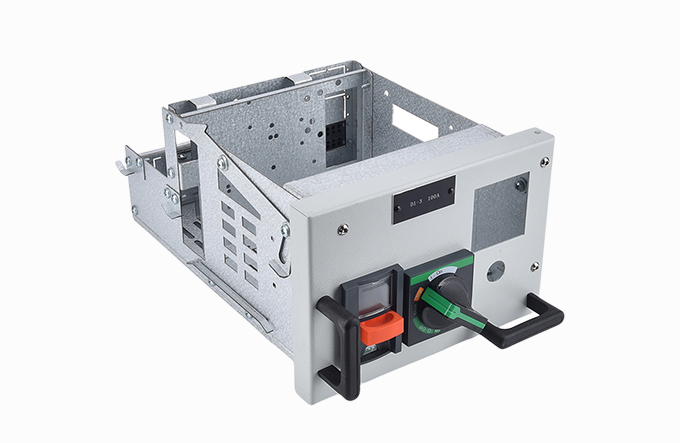
When a critical feeder trips in a commercial building, every minute of downtime bleeds revenue. Conventional fixed-mount switchgear forces maintenance crews to work inside a live enclosure, stretching a simple breaker swap into a high-risk, hours-long procedure. Drawer-type assemblies flip that script entirely. By placing circuit breakers and auxiliary devices on a withdrawable carriage that slides in and out of a compartment, they turn emergency replacement into a 10-minute job. For a real-world example of this modular approach, see MOLDVOLT’s withdrawable unit design.
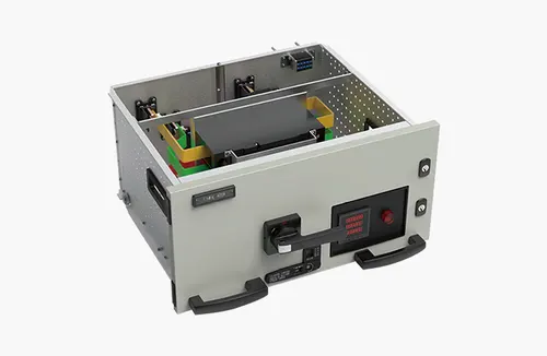
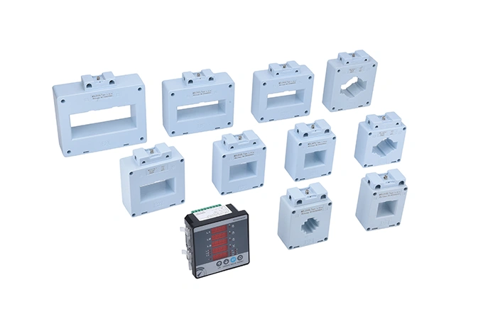
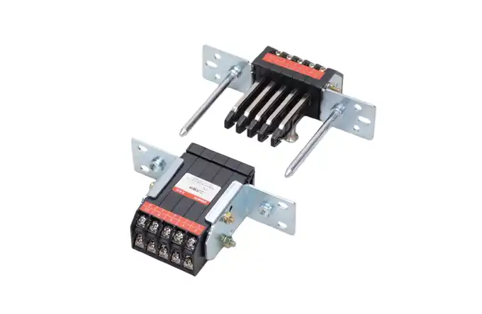
A single drawer is far more than a metal box with a breaker mounted on it. The rear side carries clusters of primary disconnecting contacts — typically silver-plated copper fingers — that mate with vertical busbars when the drawer is racked in. Secondary contacts for control wiring, communication buses, and interlock signalling ride on a separate sliding block. Every manufacturer designs its own guidance rail system, but the universal goal is the same: align the contacts to within a fraction of a millimetre under mechanical pressure, so that thermal losses at the junction stay within IEC 61439-1 limits. Drawer-type low voltage switchgear cabinets have become a staple in hospitals, data centres and manufacturing plants precisely because that precision translates into repeatable, low-resistance connections over decades of operation.
The real intelligence of a drawer cabinet emerges in its position mechanics. A manual racking screw, often driven by a hexagonal key, advances the drawer through four clearly delineated stages:
Disconnected (Isolated) – Main and secondary contacts are fully separated. The drawer can be removed without tools, completely dead.
Test – Secondary control contacts engage, powering the trip unit, communication module and metering, but the main power path stays open. Engineers can exercise breaker logic, upload setting changes or simulate trip sequences without energising the load.
Service (Connected) – Both primary and secondary contacts are closed. The breaker is live and in normal operating mode.
Withdrawn (Removable) – The entire carriage slides out of the compartment on telescopic rails, bringing the breaker to a workbench for detailed inspection.
Knowing these positions is not just academic. In a recent retrofit at a manufacturing plant, operators cut their annual switchgear maintenance window by 40 % simply by performing all trip unit injection tests in the Test position rather than de-terminating field wiring. To ensure your system incorporates these essential testing capabilities, review pre-configured safety features.
Mistakes in a live compartment cascade quickly. A well-engineered low voltage switchgear cabinet incorporates withdrawal units that lock out dangerous operations. The most critical protections include:
Breaker-ON anti-racking interlock: physically blocks insertion or withdrawal of a closed breaker, preventing arc flash under load.
Door-to-racking interlock: the compartment door cannot be opened unless the drawer is in Disconnected or Withdrawn position, and vice versa — the drawer cannot be racked in while the door is open.
Position signalling: mechanical flags and auxiliary switches tell SCADA exactly where the carriage sits, removing guesswork for remote operators.
Automatic shutter mechanism: metal shutters cover the fixed busbar contacts the moment the drawer is withdrawn, creating an IP2X barrier against inadvertent contact.
These interlocks are now mandated by IEC 61439-2 for withdrawable functional units, yet the execution quality varies enormously between fabricators. Specifiers should request a physical demonstration of the shutter action and measure withdrawal forces — anything above 250 N after 100 operations flags a binding mechanism that will cause trouble later.
The single biggest operational advantage of drawer units is mean time to repair (MTTR). A standard air circuit breaker swap in a fixed panel can take four hours, counting cable disconnection, torque checks and re-commissioning tests. With a drawer, the replacement carriage is pre-tested and pre-wired; the entire swap takes under 15 minutes. Facility managers regularly report a 60–70 % reduction in outage duration after migrating to withdrawable technology. If minimizing downtime is a priority, explore modular drawer options.
This modularity also simplifies life extensions. Instead of replacing an entire switchgear lineup when one feeder type becomes obsolete, operators replace individual drawer inserts. It is a plug-and-play upgrade path that aligns with circular economy principles — far less copper and steel end up in scrap.
“Drawer units can be hot-swapped under load.” No. Even with arc-quenching technology, IEC and NFPA 70E prohibit racking a breaker in or out while it carries load current. The Test position exists precisely so that logic checks can be done dead.
“All drawer cabinets are interchangeable.” Mechanical dimensions, contact jaw patterns and busbar pitch are almost always proprietary. Unless the specification explicitly calls for a common footprint across brands — and very few do — mixing and matching from different vendors creates misalignment and voids the type-test certificate.
“More moving parts mean less reliability.” The opposite tends to be true in properly designed assemblies. Drawer mechanisms are subjected to endurance testing (often 1,000 mechanical operations per IEC 62271-1) and experience less human error because the interlock logic enforces correct sequencing.
Specifiers evaluating a low voltage switchgear cabinet should verify that the drawers have been type-tested as an assembly, not as separate components. Ask for an IEC 61439-2 verification certificate that includes temperature-rise limits for the drawer contacts and short-circuit withstand for the entire compartment. Pay attention to paint finishes and gasketing if the lineup will live in a dusty or humid environment — ingress protection for a closed compartment door should be at least IP41, and IP54 for outdoor kiosks. Finally, demand manufacturer support for retrofitting future protection relays, as the secondary connector pin count and bus communication protocol will define the system’s upgrade ceiling.
For a comprehensive system built to international standards and backed by in-house type-test documentation, discover MOLDVOLT’s power distribution solutions. Starting with a pre-engineered but configurable platform often saves months of custom engineering and ensures every interlock and contact assembly has been proven in the test lab before it reaches your site.
References & Disclaimer
IEC 61439-2:2020, *Low-voltage switchgear and controlgear assemblies – Part 2: Power switchgear and controlgear assemblies*.
NFPA 70E, Standard for Electrical Safety in the Workplace, 2024 Edition.
The examples and performance figures cited in this article are drawn from publicly available case studies and general field experience. Readers should always consult a qualified electrical engineer for site-specific selection and installation guidance.
pubdate: 2025/10/09 2026/07/15
How to Organize Spare Parts for LV Cabinetspubdate: 2025/10/09 2026/07/07
5 Daily Checks for Drawer Switchgear – A Maintenance Technician’s Guidepubdate: 2025/10/09 2026/06/30
Solve Loose Plug‑in Contact Connection