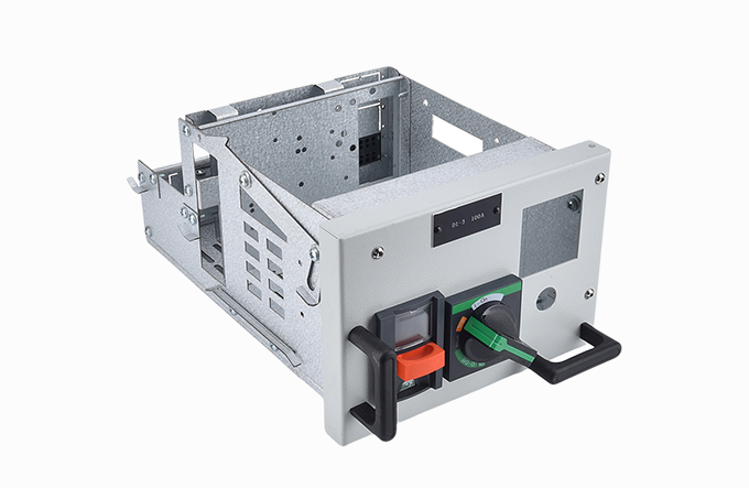
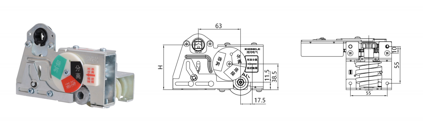
Disconnect Position: Displays "DISCONNECT" status, with both primary and secondary circuits isolated.
Disconnect → Test: Rotate the mechanism clockwise. The drawer moves and an audible "click" indicates entry into the TEST position. At this stage, the primary circuit remains isolated while the secondary circuit is energized.
Test → Connect: Continue rotating clockwise. Another "click" confirms the CONNECT position. Both primary and secondary circuits are now fully energized.
Switch Closing: Remove the crank handle. The circuit breaker can now be closed. Once closed, the handle socket is automatically blocked, preventing re-insertion.
Withdrawal: Rotate the mechanism counterclockwise to retract the drawer sequentially back to DISCONNECT. The drawer can then be safely withdrawn from the cabinet.
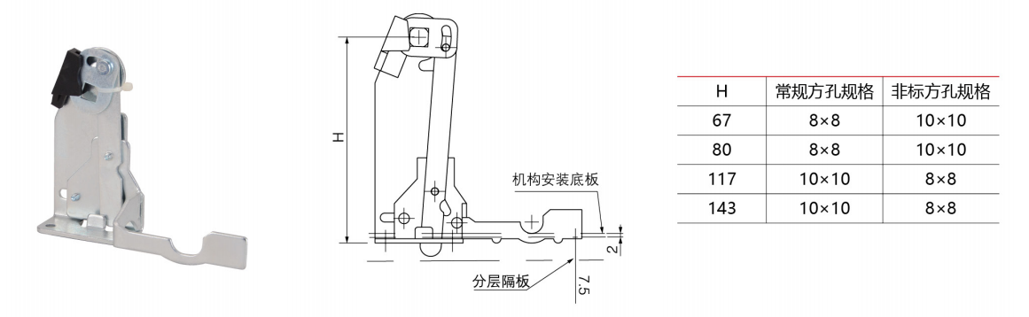
| Mechanism Selection (H) | Standard Square Rod Specification (A) | Non-Standard Square Rod Specification (A) |
| 67 | 8×8 | 10×10 |
| 80 | 8×8 | 10×10 |
| 117 | 10×10 | 8×8 |
| 143 | 10×10 | 8×8 |
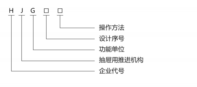
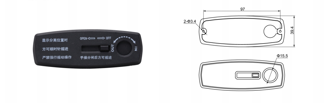
HJG-10 Operation Instructions
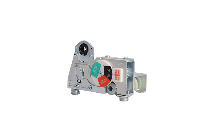
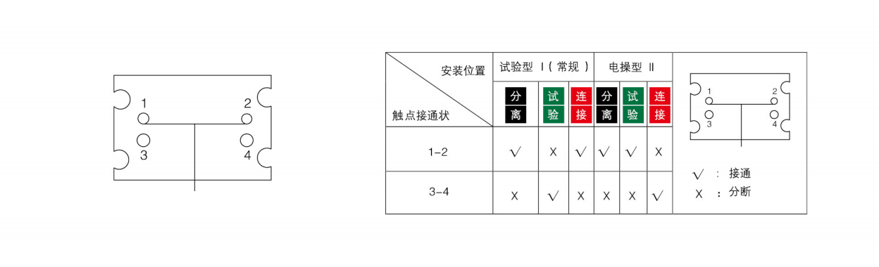
Micro Switch Operation Principle
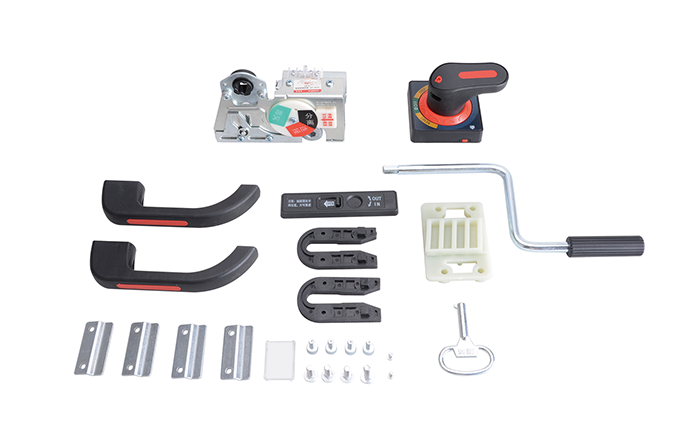
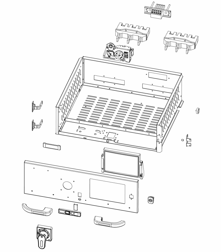
HJG-10 Hand-Crank Mechanism Drawer Assembly Exploded View
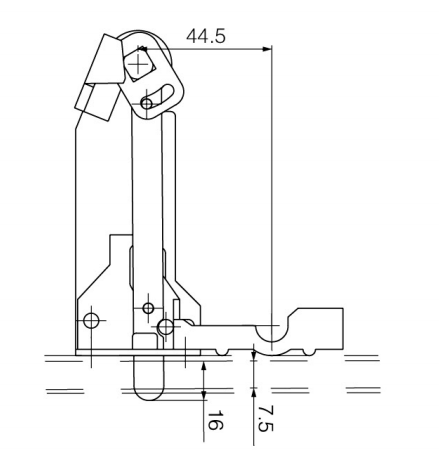
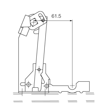
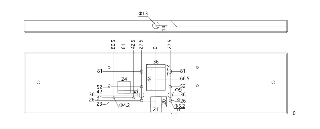
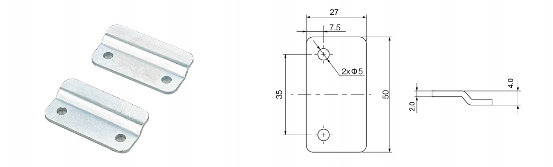
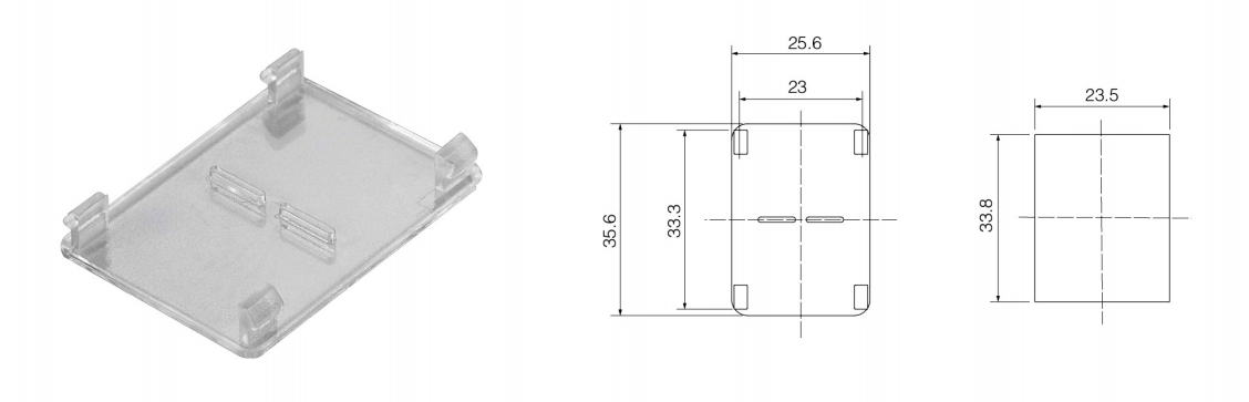
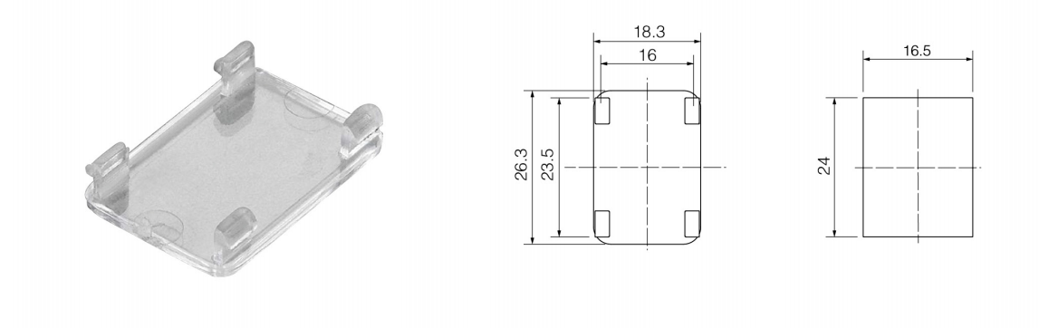
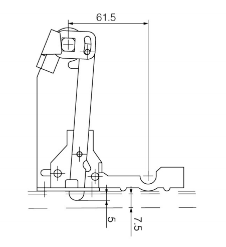
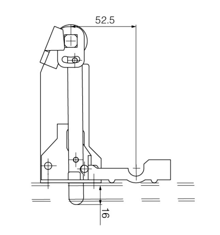
Attachment mages and Dimensions
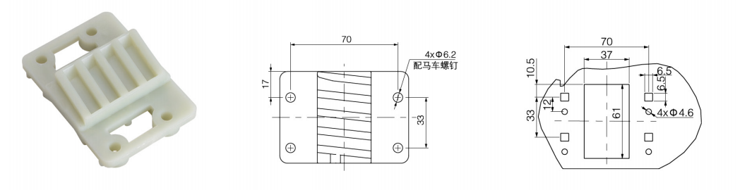
HJG-8 Cam Positioning Component (Reinforced Nylon) HJG-8 Cam Positioning Component Partition Cutout Diagram
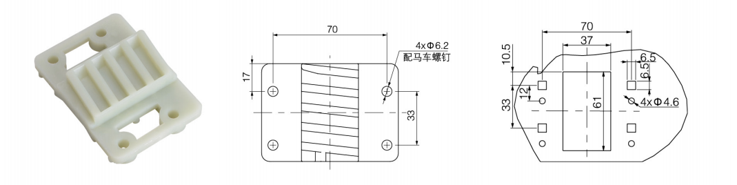
HJG-9 Cam Positioning Component (Reinforced Nylon) HJG-9 Cam Positioning Component Partition Cutout Diagram
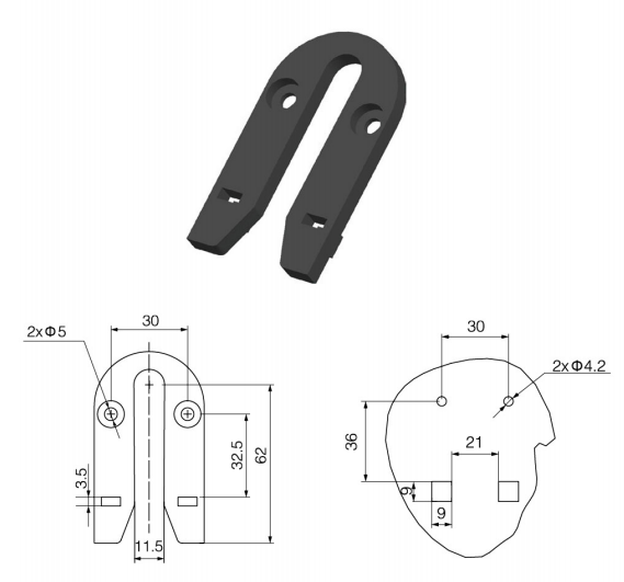
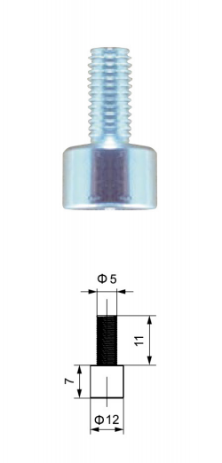
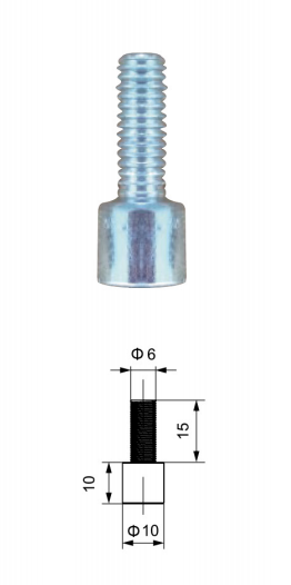
U-Shaped Guide Block M5 Guide Pin M6 Positioning Pin
HJG-8 Operation Indicator Plate
Limit Clamp (Universal Component)
HJG-9 Hand-Crank Mechanism Indicator Frame
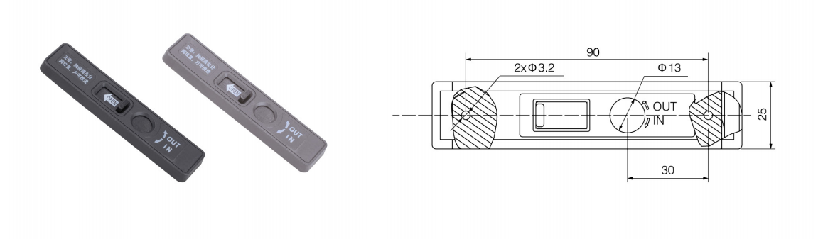
Large Observation Window (Universal Component)
Small Observation Window (Universal Component)
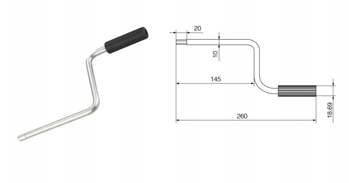
Cranking Handle (Universal Component)
HJG-8/9 Built-in Mechanism Operation Manual
Effort-Saving Advancement Mechanism Principle and Operating Procedure
DISCONNECT Position:Align to this position to display "DISCONNECT". The drawer can be cranked clockwise at this stage. Both primary and secondary circuits remain disconnected.
DISCONNECT → TEST:Turn clockwise from the DISCONNECT position until the display shows "TEST".
TEST → CONNECT:Continue turning clockwise until "CONNECT" is displayed. Both primary and secondary circuits are now energized. Remove the crank handle to close the main switch. Once closed, the handle socket is automatically blocked, preventing further insertion or withdrawal of the drawer.
Important Note:The drawer must be fully pushed into position when aligned at DISCONNECT before cranking. Do not apply excessive clockwise force when the display already indicates CONNECT position to avoid mechanism damage.
HJG-8 Closing Interlock
Open State (Breaker Off) Closed State (Breaker On)
Fault Trip State Reset State